EmbVision Tutorial: Part 5
Video Stream Processing - Simulink -
Shogo MURAMATSU and Yuki TAKAHASHI
Niigata Univ.
Copyright (c), All rights reserved, 2014-2025, Shogo MURAMATSU
Contents
Summary
Through this exercise, you can learn how to deal with videos on Simulink model and create Simulink blocks from user-defined System objects™. As well, you can also experiment simple video stream processing by using the user defined Simulink blocks.
Creation of Simulink Model
First of all, create a new Simulink model by starting with preparing a new model file.
From the HOME tag, choose the following item.
- "New"
- -> "Simulink Model"
Otherwise, use the NEW_SYSTEM and OPEN_SYSTEM function on the command window.
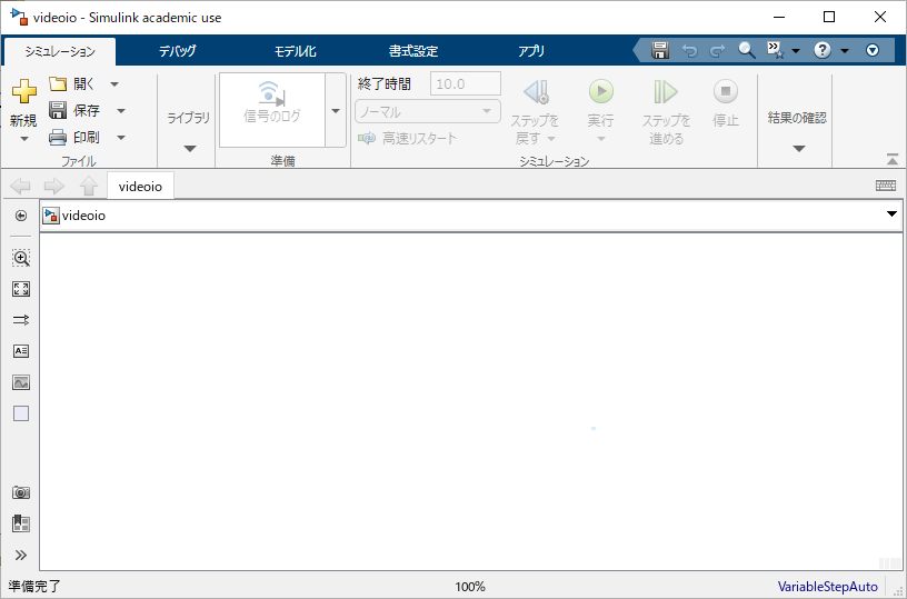
For example, create a model named "videoio" from the command window.
new_system('videoio','Model')
open_system('videoio')
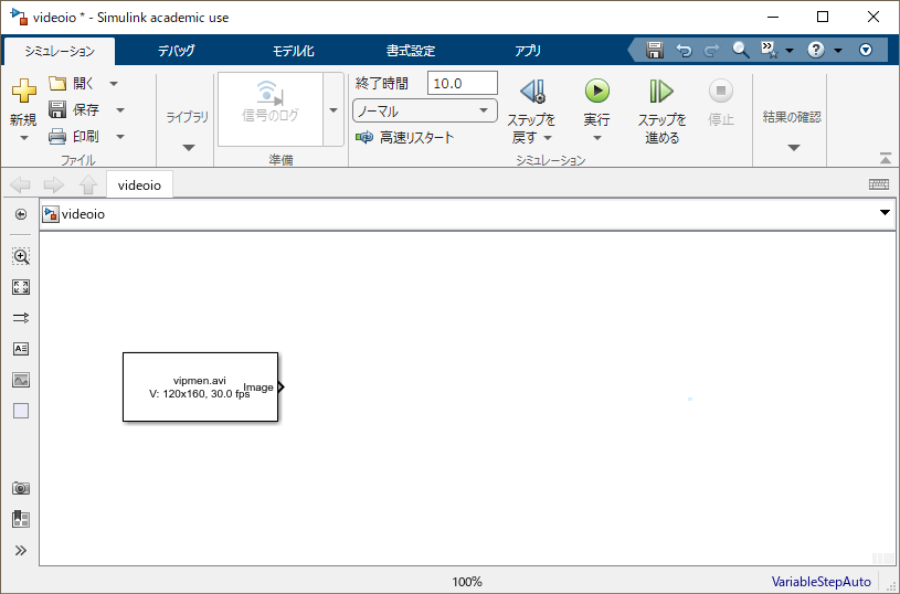
Then, a window will appearer as follows.
To save the model, click the icon

on the menu or execute the SAVE_SYSTEM function as
save_system('videoio')
on the MATLAB's command window.
[ Top ]
Simulink Library Browser
Simulink can simulate a system by deploying and connecting blocks as process components. It is possible to change properties of each block and and simulation conditions.
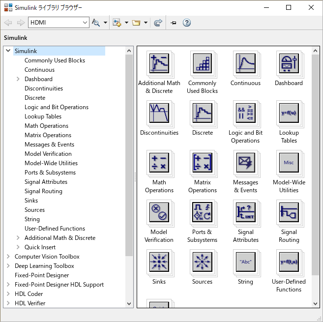
In order to use existing blocks, click the icon

on the menu bar. Then, the Simulink library browser will appear as follows.
[ Top ]
Video Input and Output Model
Next, as an example, let us create a system model which input and output video files.
Choose
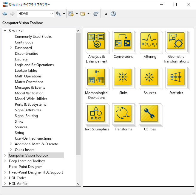
from the left list of the library browser.
Then, the browser displays a set of blocks in Computer Vision Toolbox.
One can also execute
visionlib
on the MATLAB's command window.
Double-click the "Sources" icon

from the right menu and open the block library in Computer Vision Toolbox/Sources.
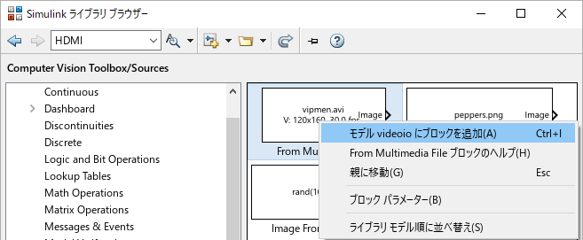
From the library, right-click the "From Multimedia File" block and add the block to model "videoio".
Then, double-click the "Sinks" icon

from the Computer Vision Toolbox library and open the block library in Computer Vision Toolbox/Sinks.
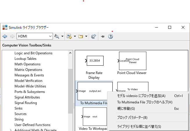
From the browser, right-click the "To Multimedia File" block and add the block to model "videoio".

Drag the output terminal of the "From Multimedia File" block to the input terminal of the "From Multimedia File" terminal to connect them.
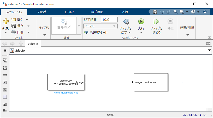
By left-clicking the run button

on the menu of the model editor, the simulation will start to run.
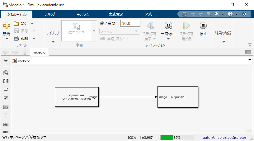
An AVI file named "output.avi" is produced. Play the video by using a tool outside MATLAB.
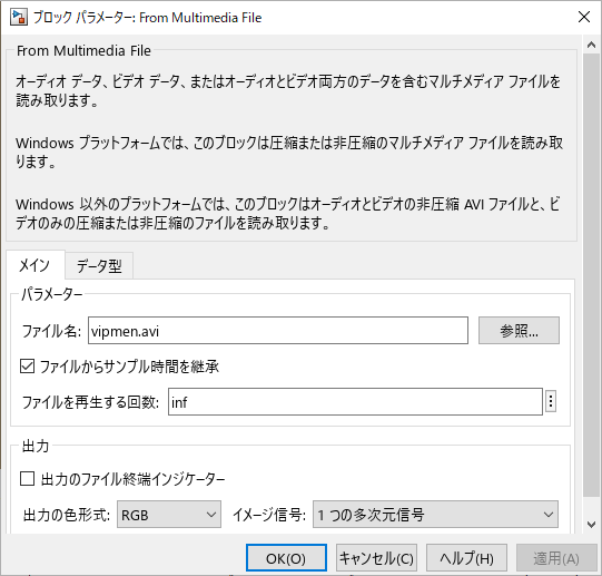
Input AVI file can be changed by editing the "File name" property on the parameter dialog which appears by double-clicking the "From Multimedia File" block.
By using the "From Video Device" block in
video data acquired from a connected camera can be used as the input.
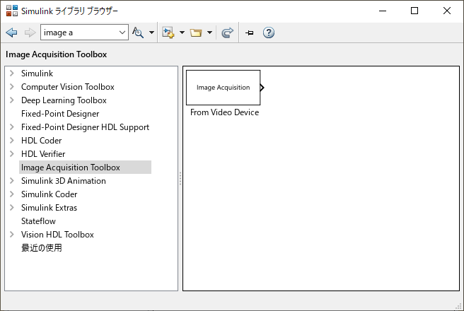
It is also possible to open the library by executing the
imaqlib
function on the MATLAB's command window. For the detail, refer to the document.
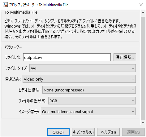
Output AVI file can be changed by editing the "File name" property on the parameter dialog which appears by double-clicking the "To Multimedia File" block.
As the output target, one can use
- Video Viewer block
- To Video Display block (only Windows®)
in the "Computer Vision Toolbox/Sinks" library. A video viewer will appear on Simulink and the output video can be monitored during the simulation. For the detail, refer to the document.
[ Top ]
MATLAB System Block
MATLAB System block enable us to define a Simulink block by using a System object.
As an example, let us defined a Simulink block by using the Rgb2GraySystem class that was created in Exercise Part3.
Save the "videoio" model as a model named "videorgb2gray".
open_system('videoio')
save_system('videoio','videorgb2gray')
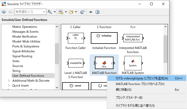
Chose
- MATLAB System block
from the "Simulink/User-Defined Functions" library and add the block to the "videorgb2gray" mode.
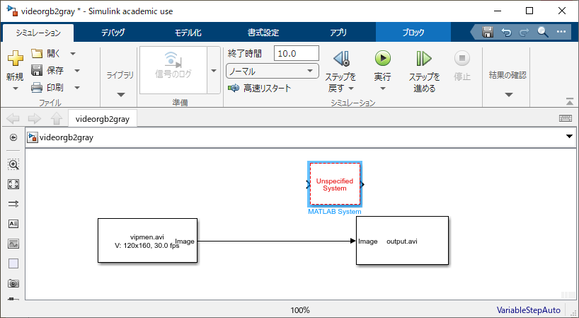
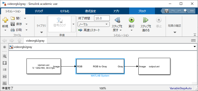
The "videorgb2gray" becomes like the following picture.
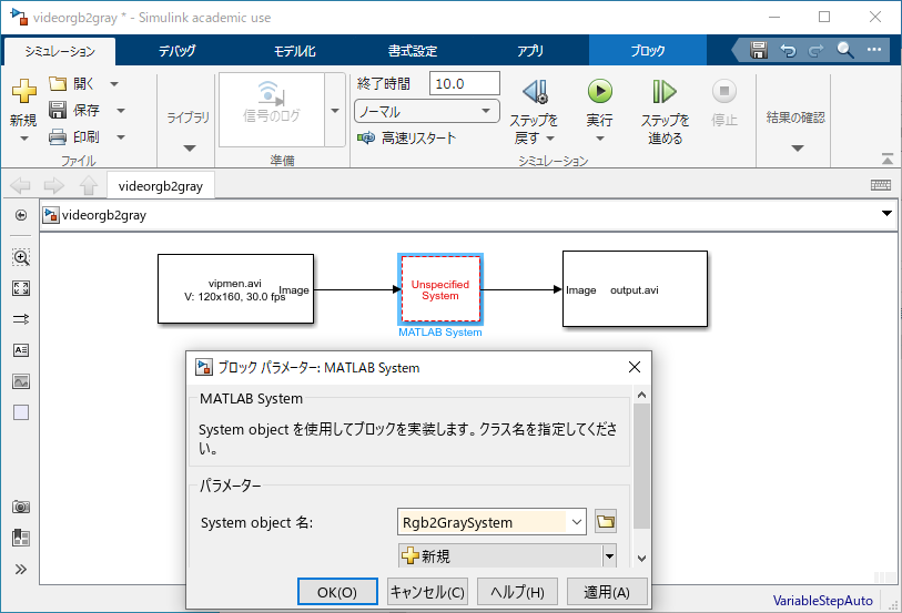
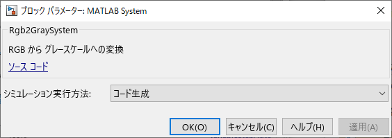
Insert the MATLAB System block between the video input and output blocks. Then, open the property dialog and set the property as follows.
- System object name: Rgb2GraySystem
By clicking the "OK" button and appropriately stretching the center block, one can obtain a model looks like the following picture. ��ԂƂȂ�B
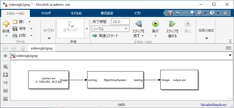
Run the model and verify the AVI file "output.avi".
[ Top ]
Customization of Icon
Input and output names of an MATLAB System block can be customized by the definition of the original System object.
Let us set the names of input and output ports. One can open the source code of the Rgb2GraySystem class from the block parameter dialog.
Next, add the following method
methods (Access=protected)
   ...�i�ȗ��j
   % # of input ports
   function N = getNumInputsImpl(obj)
       N = 1;
   end
   % # of output ports
   function N = getNumOutputsImpl(obj)
       N = 1;
   end
   % Names of input ports
   function inputName = getInputNamesImpl(obj)
          inputName = 'RGB';
   end
   % Names of output ports
   function outputName = getOutputNamesImpl(obj)
          outputName = 'Gray';
   end
   ...�i�ȗ��j
end
to the methods(Access=protected) section.
Furthermore, by extending the
class, one can customize the icon on the simulink mode editor.
First, revise the first CLASSDEF line of the source code as follows.
classdef Rgb2GraySystem < matlab.System ...
      & matlab.system.mixin.CustomIcon
Second, add the following method
methods (Access=protected)
   ...
   % Icon
   function icon = getIconImpl(obj)
      icon = sprintf('RGB to Gray');
   end
   ...
end
to the methods(Access=protected) section.
Click the "OK" button to close the dialog. Then, the names of the input, output and icon in the center block become as indicated in the System object definition.
[ Top ]
Precision and Propagation (Option)
(Under construction)
Feed Through (Option)
(Under construction)
[ Top ]
Exercises
Exercise 5-1. Prewitt Gradient Filter
By using the following System object classes
* Rgb2GraySystem
* GradFiltSystem
* Hsv2RgbSystem
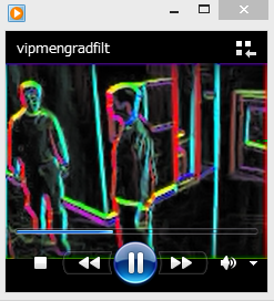
which are created in Exercise Part 4 as MATLAB System blocks, create a Simulink model of the following MATLAB code.
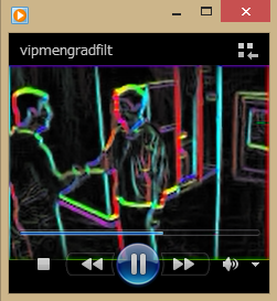
vrObj = VideoReader('vipmen.avi');
frameRate = get(vrObj,'FrameRate');
vwObj = VideoWriter('vipmengradfilt.avi');
set(vwObj,'FrameRate',frameRate);
rgsObj = Rgb2GraySystem();
hrsObj = Hsv2RgbSystem();
gfsObj = GradFiltSystem();
open(vwObj)
while (hasFrame(vrObj))
   frame     = readFrame(vrObj);         % Read frame
   graysc    = step(rgsObj,frame);       % Convert to grayscale
   [mag,ang] = step(gfsObj,graysc);      % Apply gradient filtering
   ang       = (ang+pi)/(2*pi);          % Normalize the direction
   mag       = min(mag,1);               % Saturate the magnitude
   [r,g,b]   = step(hrsObj,ang,mag,mag); % Convert to pseudo color
   frame     = cat(3,r,g,b);             % Concatenate RGB array
   writeVideo(vwObj,frame);              % Write frame
end
close(vwObj)
(Example Model)
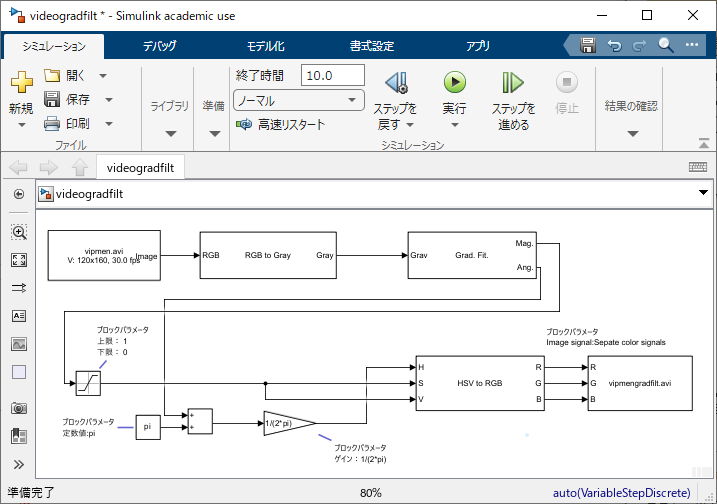
In the above mode, the following existing blocks were used.
(Example Answer)
Exercise 5-2. Sobel Gradient Filter
Change the filter kernel of the Prewitt gradient filter model developed in Exercise 5-1 to Sobel Kernel described in Exercise 4-1. Then, run the simulation of the model.
- Hint: Revise the "Kernel" parameter of the GradFilterSystem block.
(Example Answer)